new 8/8/03, updated 4/10/2006
I just had the terminal on the alternator pull out and melt down. Pretty
neat stuff, except the car died with little to no warning as the cable
burned off the alternator then was seeking out ground and hence the car
only when about half a mile after the battery light came on for me.
Regardless she is fixed now. I had read Paul's listing of what to do to
replace the alternator with great interest, and was upset about having to
lower the subframe as it may have affected the alignment I just got done. To
make a long story short I had the bad alternator laying on the driveway in
about 25 minutes.
Tools needed:
8 mm socket or wrench
10 mm socket (shallow)
14 mm socket (deep)
14 mm ratcheting end wrench would be very cool but not required - I did it
without it but it would have been nice.
18 mm socket
pliers
If you arms are skinny enough you can do this without removing the cowl, it
isn't pleasant but I did it.
1) Disconnect battery positive cable (8 mm)
2) On top stud of alternator is a metal bracket that supports the
alternator output wire, remove the 10mm nut retaining this bracket
3) Jack car remove RF wheel (place on a stand of course)
4) From underneath using 10mm disconnect Alternator output wire - pull wire
up out of the way and lay it on top of the engine or PS reservoir someplace
5) Deal with serpentine belt and get it out of the way and off of the alt.
6) Remove Tie-rod end from knuckle (requires a pliers for the cotter pin,
and an 18mm) -position tie rod out of the way. (aft)
7) Unplug cable harness from alternator
8) Now for the fun! Remove (2) 14mm studs and a bolt that retain the alt
(the top one is lots of fun, I fished my ratchet down from the top, then
got it on the head, then handled the ratchet from below.
9) Fish alternator out through the hole in the wheel well (this requires a
minute or two of finesse and your geometry classes may come in handy just
like bringing a couch into a house), turn the RF knuckle to the left this
will bring the end link out a bit farther and get you a little more
room. It is tight but does come through; be careful of the brake line.
Install is roughly the opposite of the removal - you should have it figured
out by now, make sure the pulley on your replacement alternator is the same
size, if it isn't swap them over at your auto parts store. I had this
whole thing done in about an hour and 15 minutes of actual work time, but
my arms are scrawny enough that I didn't have to pull the cowl, the R&R of
that is another 10 minutes or so.
Have fun,
Scott Krietemeyer
96 MG
Sure, easy for you, Scott, you have skinny amrs!! Nice job. Larry
________________________________________________________________________
04/10/2006
FPN sent a second alternator out to me after the first one was damaged
in transit. They sent a return UPS label so all I had to do was slap
it on the box and drop the broken alternator off at the UPS store.
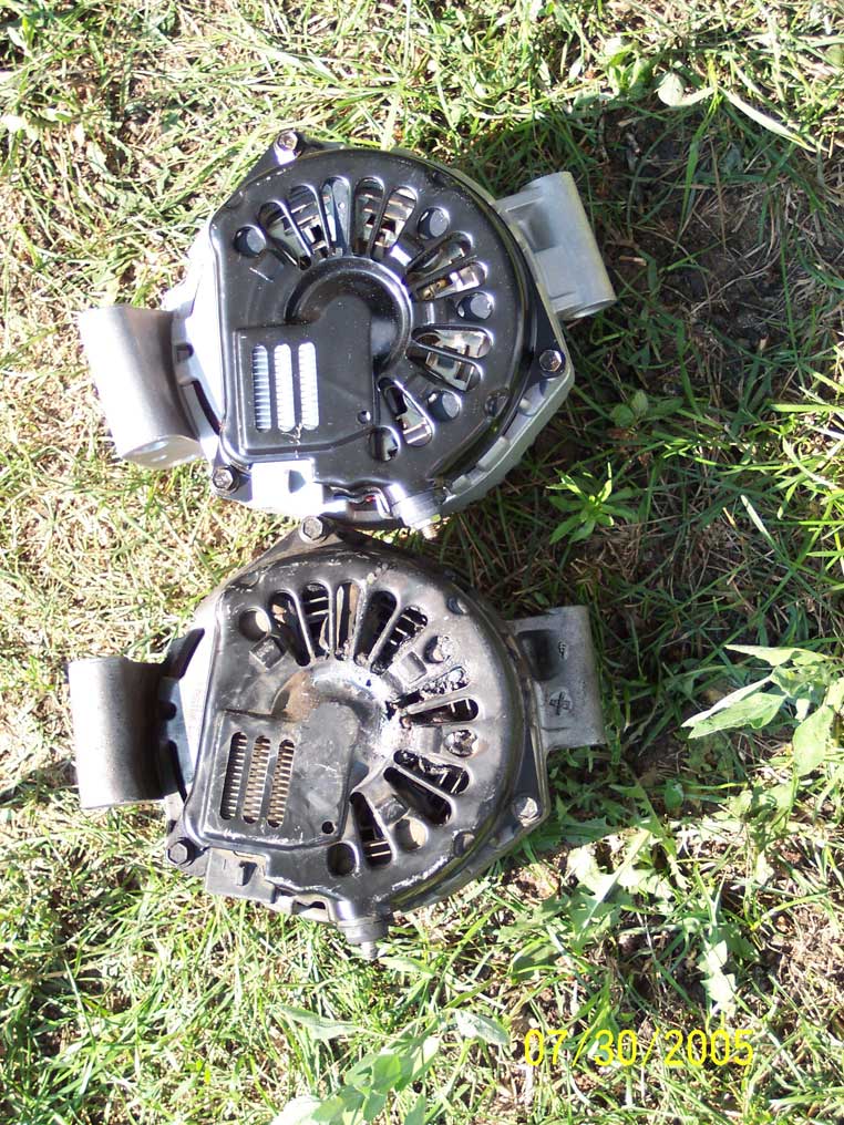
The second alternator looked to be the same as the first one (sans the
damage, of course). Both had the correct pulley and correct part
number on the box.
I used Scott's method for the R&R procedure, which enabled me to leave
the subframe alone.
http://www.v8sho.com/SHO/AlternatorReplacementScottStyle.htm
I did have to remove the passenger side cowl to free up that stubborn
and elusive top bolt. Even then, I couldn't get at the box wrench
from the proper angle to put the requisite 100+ lb-ft of torque on it
to break it loose. So I carefully inserted the box end of the 14mm
wrench on the top bolt, with the offset angle of the wrench head
oriented so that the wrench was basically vertical. Then I used the
old serpentine belt to pull on the wrench while I stood next to the
driver side of the car. Worked like a charm! After that initial jerk
to bust the bolt loose, it unscrewed easily by hand, since I had left
the bottom bolts installed to hold the alternator in place.
The old one came out easily after that. I simply rotated the
alternator so that the pulley was facing about 10 o'clock as viewed
from the passenger side, and the mounting bosses were facing straight
out at me. I turned the wheel/hub as if to make a RH turn, thus
getting the end link out of the way. The new one went in the same
way.
I used bolt cutters and a grinding wheel to reduce the threaded stud
on the top bolt so that it only protruded about 1/4". This would
enable a common (shallow) 6-pt 14mm socket to be used on that bolt in
the future, while still allowing enough thread length for the
alternator wire bracket to be secured.
After thinking about what things could possibly go wrong to cause
these alternators to go up in smoke prematurely, I decided a little
anal retentive behavior was in order when installing the new
alternator.
Idea #1 was that a weak electrical connection at the main positive
cable might impart too much resistance for the alternator to handle.
So I used 600 grit sandpaper on both sides of the ring terminal to
make a good clean connection. Then I used a liberal application of
dielectric grease to make sure it couldn't corrode (esp. since the
boot was partially ripped from the removal procedure.)
Idea #2 was a follow-up on #1. I used the 600 grit paper for the
three mounting locations on the alternator bracket to ensure a good
ground connection. I wire brushed the threads of the bolts, and gave
them a tiny dab of anti-seize (which is conductive) on the threads and
on the bolt flanges that press on the alternator mounting bosses.
Then I sprayed the 3-conductor plug on the car with Wire Dryer, and
used dielectric grease around the perimeter of the female connector on
the alternator before mating them up. No moisture is going to be
getting into any of these connections!
Routing the serpentine belt was fun. :-| Once I finally had the belt
routed around everything but the crank pulley, I used a 1/2" drive
ratchet wrench with a 3/8" reducer and a 12" long 3/8" drive wobble
extension to work the tensioner. There is a hole in the bottom edge
of the wheel well opening that offers a great pivot point for this.
So I was able to use my knee to push up on the wrench and then I could
use both hands to get the belt routed around the crank pulley.
I triple checked the belt routing and alignment on the various pulleys
before buttoning everything up and putting the battery on
trickle/float charge overnight. Started it up this morning and it
instantly went up to 14.405 volts and held rock steady. :-) After
letting the PCM re-train itself, I took it for a spin and confirmed
that the voltage stayed steady from 700 rpms to 7200 rpms. At idle,
in drive, with MAX A/C and High Beams on, it holds at about 13.9V.
So far, so good... I'll update when/if anything changes.
--
Dan Carman
'97 PG
Philadelphia, PA
________________________________________________________________________
Give it a couple of weeks before formally declaring victory.
:-)
Eric
__________________________________________________________________________
Yeah, so would I!!!!!