
new 10/10/01
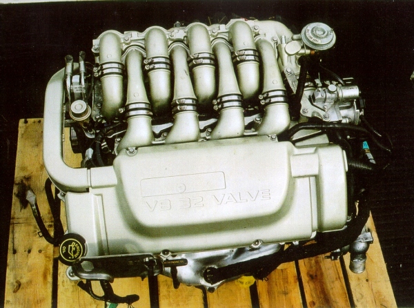 |
1) The engine before disassembly |
 |
2) ID numbers for this engine. Could this be used to help document failed engines? The engine came out of a 1996 SHO with 57,288 miles. Build date was 4-24-96. Warranty start date 4-29-97. |
 |
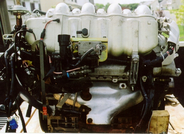
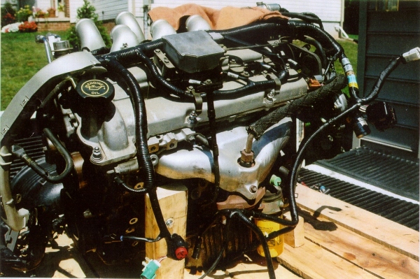
3) Left side of engine |
 |
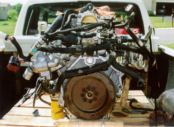
4) Rear view of engine. |
 |
5) Front view after partial disassembly. |
 |
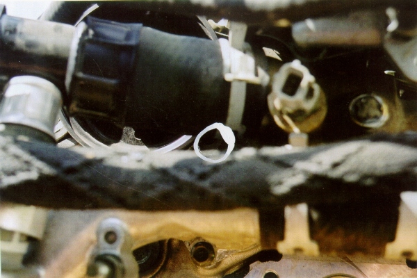
6) This is the oil plug for the rear cylinder head intake cam. Since there is some concern about oiling to the heads you could remove the 4 plugs and install copper tubing and mount 4 small oil pressure gages. Then you could compare oil pressure to all 4 cams. This may sound a little extreme, but might help pinpoint a problem and save an engine. |
 |
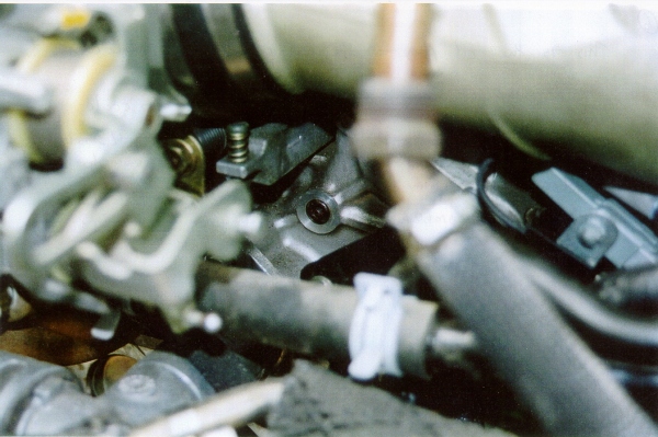
7) This is the oil plug for the rear cylinder head exhaust cam. It is kind of buried in the vehicle. You can measure oil pressure here if you suspect an oiling concern to the camshaft. It is located on the left side of the engine, right above the transmission. |
 |
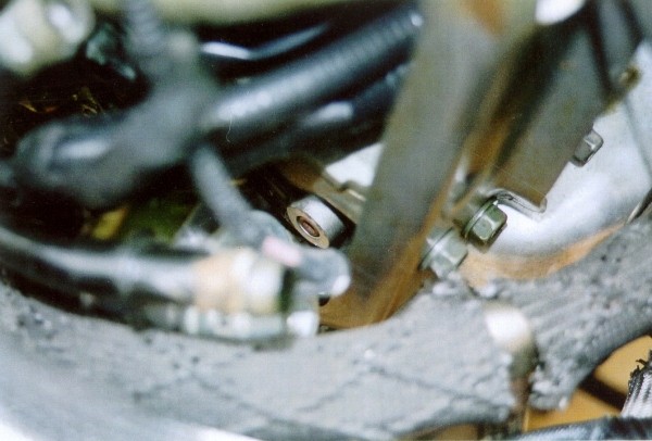
8) You can’t see it in the picture but this is the location of the oil plug for the front cylinder head exhaust cam. It is behind the water pump pulley |
 |
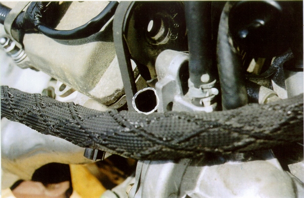
9) This is the oil plug for the front cylinder head intake cam. It is located behind the coolant hose, near the temperature sending unit for the PCM. |
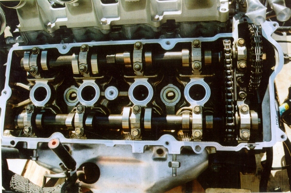 |
10) This is a picture of the rear cylinder head before removing the camshaft. Notice the bright spot just behind the second gear on the intake camshaft. This is what wears. |
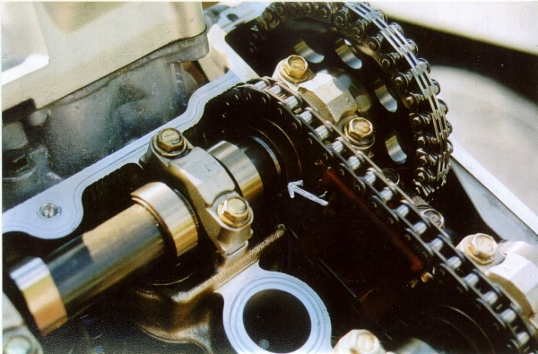 |
11) The shiny part next to the inner gear is where the camshaft gear gouged into the camshaft. The gear worked it's way loose and stopped moving, causing the exhaust camshaft to stay put.. The intake camshaft which is shown, keeps moving, grinding the splines on the gear. |
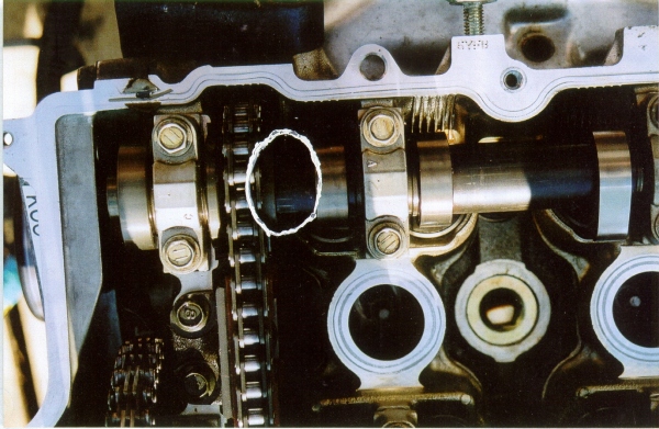 |
12) See the marks in the circled area. These marks that are left when the gear is pressed on to the cam. There are no splines on the camshaft, only splines on the gears and lobes. This may be OK for the lobes, but it seems like a weak point when it comes to the camshaft gears. |
 |
Here is a sketch. |
 |
13) Check out the valve clearance. At least 1/4". These valves are bent on the exhaust side of the rear cylinder head. |
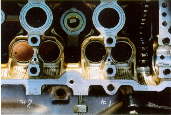 |
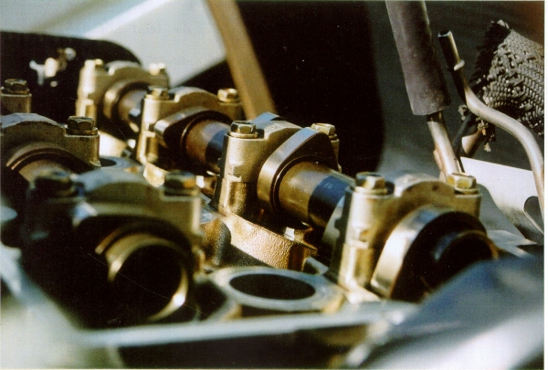
14) Here is a picture of the lower camshaft journals for the exhaust cam in the rear head. Notice there is not a whole lot of surface area for the camshaft to ride on. I would think tat this makes it a whole lot harder for the cam to "lock up" due to oiling problems. This shows the journals for cylinders #1 & #2. More accurately, the first 3 journals on the camshaft. It does not look like there was an oiling concern on this engine. |
 |
15) Camshaft journals for cylinders #3 & #4. |
 |
16) This is the rear exhaust cam and respective upper journals. There are no bearings in this setup. The camshaft rides right on the aluminum. It does not appear to have any oiling concern. Camshafts and journals look good. |
| 17) Here is the the intake cam and journals for comparison to the exhaust cam. Wear looks about the same between both camshafts. I do not believe there was an oiling concern with this engine. it seems like the failure was the inner gear on the intake cam. I feel the cams could be made stronger by having splines both on the camshaft and sprocket. For now, welding the to the cam seems like a good fix. | |