
Updated 10/3/2003
An Overview
Anti-Lock Brake System (ABS) Vehicle Speed Input Signal (SHO Only):
The anti-lock brake system uses two sets of variable reluctance speed sensors (two front and two rear) to determine vehicle speed. Four anti-lock sensor indicators (one each wheel) rotate past each wheel speed sensor. The signal generated is proportional to wheel speed and is sent to the anti-lock brake control module. A vehicle speed signal is then broadcast by the anti-lock brake control module on the Standard Corporate Protocol (SCP) Data Link to the powertrain control module as a vehicle speed input signal
Paul Nimz
'97 TR
'93 EG mtx
_____________________________________________________________________________
The Details
The anti-lock brake system operates as follows:
It uses four variable-reluctance brake anti-lock sensors and brake anti-lock sensor indicators to determine the rotational speed of each wheel.
Sensors operate on magnetic induction principle.
As the teeth on the brake anti-lock sensor indicators rotate past the brake anti-lock sensors, a signal proportional to the speed of the rotation is generated and sent to the anti-lock brake control module through a twisted pair harness.
Front
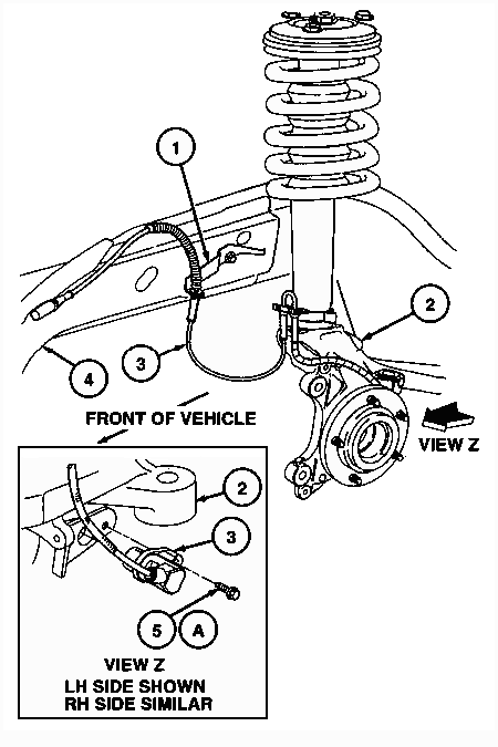
The anti-lock brake control module front brake anti-lock sensors are bolted to the front wheel knuckles. The front brake anti-lock sensor indicators are pressed onto the outer CV joints.
Front Anti-Lock Brake Sensor

Rear
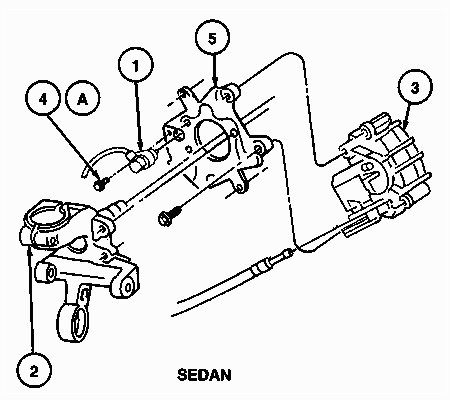
On sedans, the rear brake anti-lock sensors are attached to the right hand rear disc brake adapter and left hand rear disc brake adapters.
The rear brake anti-lock sensor indicators are pressed onto the wheel hub assemblies.
Rear Anti-Lock Brake Sensors
