new 11/04/2003
Note from the webmaster: This thread took many turns. Some good, well some maybe not so good. I have edited the content to focus on what, at least for me, was some interesting information. It is posted only for it's informational value only.
Uncl Lar
Anyway I did take a good cam and destroyed it, to show what I'm talking
about.
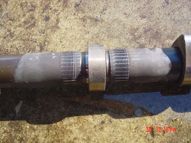
If you (the list) take a good look you will see the splines or threads on
the shaft. The lobe is beat off in one direction to cause as little damage
as possible. The cam IS splined first, and then the lobe is placed over that
area then expanded into the teeth of the sprocket. You will see the sliding
marks from the teeth on the shaft and through the splines. It is straight as
the way it was put on.
The horizontal lines are from the teeth of the sprocket
The vertical lines are the splines that are made as part of the cam.
This SAME process is under the sprocket too
The rest will be on V8SHO later tonight or tomorrow. My picture skills are
POOR so some of the pictures are blurry. This one though is real nice
Kirk J Doucette
Holy cow, both knurled parts do not make for a large surface area of contact for those two parts! It's no wonder the sprockets are slipping.
FWIW, the cam "threads" are actually called straight knurls. Not busting chops, just looking to inform.
Robert, the process you are referring to is called forging. That's how most
one piece cams are made. IIRC, back in the late 70's/early 80's, GM used a
cast iron cam in their 3.8l V6, and had a lot of trouble with the lobes
wearing too quickly.
The process of forging is basically a two part die that stamps the rough
form of the finished part out of a billet blank. Journals, lobes, and gears
are then machined on the rough forging.
Bob
Composite cams are rapidly becoming the norm. The advantages are numerous:
1) Different materials with different wear and strength properties can be used for different pieces of the cam. Sprocket and cam lobes can have different hardness ratings, and the cam tube can be made of less brittle material so it is more reliable.
2) Less material waste during manufacturing
These are big glaring advantages to composite cams. A quick google for composite camshaft will provide more information.
Of course none of this matters if the design is screwed up (like the V8's).
Scott
Those marks are just that...marks, made by the underside of
the lobe/sprocket. If you line up the part that you cut off, you will find they line up EXACTLY and mate EXACTLY!
These are what is left when the shaft is expanded into that underside of the lobe and sprocket.
NOTE, that there is no spiral thread, there is no indication that the part is spun onto those marks and there is no way that you can slide that part onto those marks.
Don
The splines that Kirk is talking about are the lines that run around the circumference of the camshaft. Unless your eyes are REALLY bad, they are EXTREMELY visible in the version of the photo that I got.
The lines that run in the direction of the axis of the shaft are from the expansion into the lobes.
It seems that we're mixing terminology, which is obfuscating the issue.
I see knurling around the circumference, *which is what Kirk has been talking about all along.*
I also see marks from the lobe interference fit, in the direction of the axis.
I call a Tie.
-John Breen III
second the motion.
They are not "threads" as it is not just one cut around the shaft there are several. There also is Way more there on the shaft than nothing. I wonder if it was done this way so that they could mark where on the shaft each lobe and sprocket goes by covering up all of the "knurling" with the subject lobe or sprocket.
I also agree with Bob, if they have small raised splines on both sides of the interference fit no wonder the puppies don't hold up, as you are reducing the amount of metal to metal contact with those raised splines in perpendicular directions.
Not threads and WAY more than nothing.... Previously I had always thought that the cam tube surface would be totally unmodified, obviously that isn't the case.
So the next question is when do we see one of these cams where a lobe comes free and "spins like a top". They have 1/4 the number of impacts per rev. and 1/8the the torque applied every rev, I suppose that suggests that the mean failure point there would be 60K *4 *8 which would be at about 2,000 K so probably not much to worry about huh (simple math employed your mileage may vary).
Scott Krietemeyer
One part of the sprocket design that contributes to failure is the asymmetrical load. I bet the cams lobes are loaded more symmetrically, which would add to their longevity???
Best Regards,
Doug
Less mass would also allow the component to accelerate faster. Interesting
concept on a cam really.
Bob
The lines that are parallel to the cam tube centerline are
from the ID of the lobe. The lines that run the circumference perpendicular
to the cam tube centerline are knurled onto the cam tube. It's sort of like
having a machined raised area for the lobe to seat on, except in this case
they chose to knurl the tube to raise the material, thus increasing the OD
of the tube in that one area. Knurling a shaft to raise material is a
common practice on assemblies such as this, for cost reasons and also ease of assembly.
Judging by the amount of material that was displaced by the lobe knurl, if
the cam tube was the same size for its entire length, the lobe would have gouged lines along the entire surface of the cam tube when assembled.
Bob
Thanks for the earlier correction, I wasn't sure what to call it. I looked
good at it today for signs of a thread pitch, there is a section where it
looks like it could be but then it all looks straight.
My thought is that this knurling, has specific spacing. During the assembly
process it would make things much easier to hold the lobes in place. It
totally makes sense, as much sense as a swedged cam does I guess :)
Bob, I should have had you inspect the cam too while you were up here today.
I totally forgot about the cam being on the bench, it was by the fuel pump
assembly that was all torn done for some inspection.. Ever see the 3rd GEN
fuel management system all torn apart? Its pretty cool compared to all the
other Gen Taurus's , works the same way as the 98 and up Cobra mustangs, and
explains why you can go so far on a Low Fuel light. Also why you physically
can get air in the system on a low tank during lots of corners on a track.
Anyway Back on topic.
The wrecked cam will be going out to the Fab shop to be split tomorrow.
Kirk J Doucette