Home | Mailing List | Specifications | Care and Feeding | Modifications | Vendors | Literature
New 02/25/52005
Hello all!,
I've written about this in the past but, believe, I've got a more definitive
angle to my SHO's problem.
The battery light comes on intermittently. I've taken it to AutoZone to have the
alternator tested and they claim it tests good (good diode pattern, 120 amps,
14+volts). Only problem is that when they tested it the battery light was NOT
on.
Well, after carting around a multi-meter for two weeks I finally was able to
test voltage while the battery light was ON. For about 30 seconds with the
battery light on steady, the alternator was pumping out 14.2 volts. For this
reason I'm concluding the alternator is okay and what I have is an indication
problem.
I imagine that the battery light is powered by a solid state transistor that
senses voltage and sends power to the light when voltage drops below a certain
threshold. My question is: Can anyone help me locate this solid state
transistor? Is it replaceable? (Am I on the right track with this?)
Any help is appreciated.
Ryan
'97 SHO red (welded)
______________________________________________________________________
Only a resistor in the dash. Same old circuit they have used for years.
Paul
______________________________________________________________________
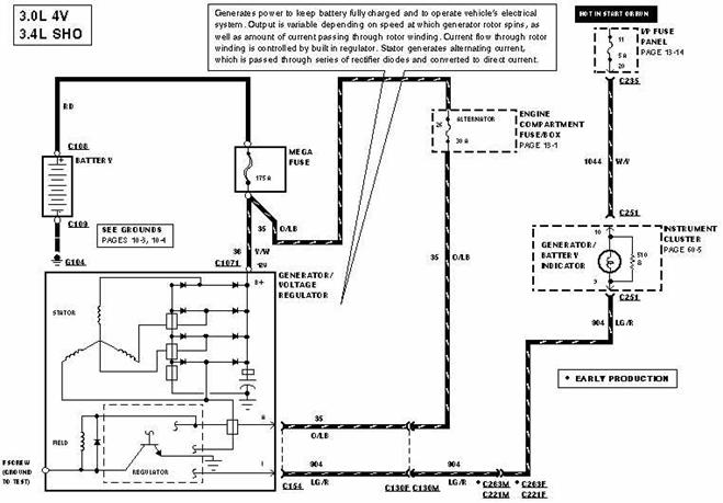
Charging System
The charging system is a negative ground electrical system consisting of:
• generator (GEN) (10346).
• voltage regulator (VR) (10316).
• battery.
• associated wiring.
Generator
The generator (GEN) (10346):
• supplies current to the vehicle's electrical system.
• charges the battery (10655).
With the ignition switch in the RUN position:
• voltage is supplied through the I circuit to the voltage regulator (VR)
(10316).
• the generator warning indicator turns on (lamp prove-out).
• the voltage regulator turns on, allowing current to flow through the A circuit
to the generator field coil.
With the engine running:
• the generator produces alternating current (ac), which is changed to direct
current (dc) by the rectifier diodes.
• current is supplied to the vehicle through the generator B+ terminal (stud).
• The generator warning indicator turns off.
• Generator output is controlled by the voltage regulator.
Voltage Regulator
The voltage regulator (VR) (10316):
• adjusts the generator field current to increase or decrease generator output
current.
• sets the generator output voltage.
• turns the generator warning indicator on when a problem is detected in the
charging system or associated wiring.
The generator output voltage will vary with temperature. The output voltage is
typically higher in the winter (cold) and lower in the summer (hot).
The voltage regulator will turn the generator warning indicator on for the
following conditions:
• ignition switch in the RUN position with the engine not running. This is the
lamp prove-out (does not indicate a problem with the charging system)
• open in the A circuit
• inoperative generator (GEN) (10346)
• generator output voltage too high
Refer to Section 14-00 for diagnostic procedures if the generator warning
indicator stays on with engine running.
With the system functioning normally:
• the generator output current is determined by the voltage of the A circuit
(battery-sense voltage).
• the A circuit voltage is compared to a set voltage internal to the voltage
regulator. The voltage regulator controls the generator field current to
maintain proper generator output.
• the set voltage varies with temperature and is typically higher in the winter
than summer, allowing for better battery charging.
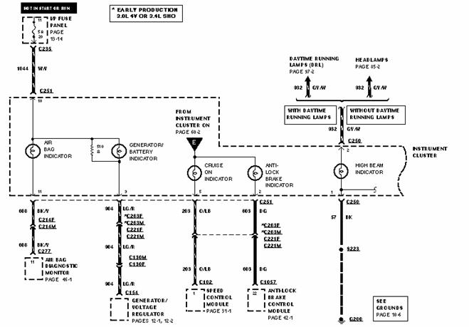
The generator warning indicator comes on when a problem is detected in the:
• generator.
• voltage regulator.
• associated wiring
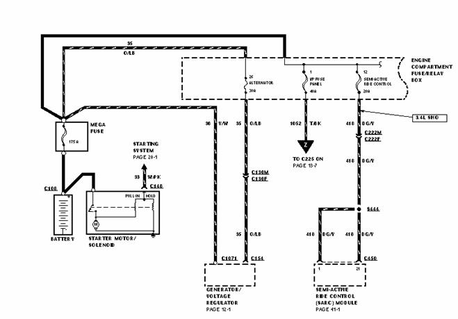
Generator Circuit
Battery Positive Voltage (B+) Output
The B+ circuit, Circuit 36 (Y/W):
• supplies the generator output current to the power distribution box.
• is always hot.
I Circuit
The I circuit, Circuit 904 (LG/R):
• turns the voltage regulator (VR) (10316) on when the ignition switch is in the
RUN position.
• turns the generator warning indicator on if there is a problem in the charging
system or associated wiring.
A Circuit
The A circuit, Circuit 35 (O/LB):
• is used by the voltage regulator to sense battery voltage.
• supplies current to the generator field coil.
• is always hot.
• is protected by a fuse in the power distribution box.