
Home | Mailing List | Specifications | Care and Feeding | Modifications | Vendors | Literature
new 07/06/2004
OK today I got into the trunk and here's the story.....
It is indeed a small red with pink wire that is cut and a switch is inserted to
control the antenna. When switched this way it will go up if the radio is on and
go down when switched off or when the circuit loses power.
There is a bundle of 4 wires, dark green (DG), black (BK), red&pink (R/PK) and
red&black (R/BK). Here is the wire diagram.
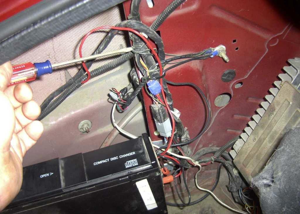
Here I am pointing to where the small bundle comes out of the main loom.
And here is the splice, I uses small gray wire nuts to splice the 20 ga white twin lead to the cut red/pink (R/PK) wire.
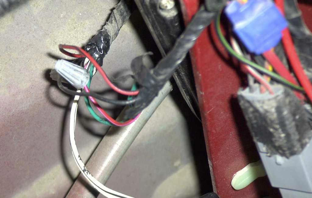
The blue tap is for my amp turn on power.
Paul Nimz
Note: This is the wiring for a 97, it should be the same for all years.