
When the Generation 3 SHO was designed, Ford conveniently left out the driving or fog lights that were standard issue on the first two generations. Likewise, there are very few options for adding aftermarket lights to the 96 - 99 SHO's due to space requirements. Al Primm offers his solution outlined below for installing a particular pair of aftermarket lights on his 97. I followed suit and installed a similar set on my 96 in a similar fashion.
I picked up a set of RALLYE "Eclipse" low profile driving lights. Driving light is model # 3243, the fogs are model 3241. The size of the lens closely approximated the upper gill slit in the front, and I didn't want to piss away a lot of money for something that didn't fit, so that explains my choice. Cost was 37.50 at a NAPA dealer, somewhere in Rhode Island.
I removed the air dam, lower air pan, and lower fasica. This required
a Phillips screw driver, a 5.5 mm socket (I think, Id have to go dig it
out), a 9 mm socket, a 3 foot piece of coat hangar wire cut off with a
sharp point, ramps, work light, working pad to lay on... In addition, you
will need at various times a straight slot screwdriver, a Drill motor with
assorted SHARP drill bits, in particular the 3/8 bit. Several smaller
bits for drilling
screw holes are appropriate.. Did I mention SHARP?
PLAN #1
After removing the lower front of the front end, you can access the
bumper reinforcement beam. Initially I intended to mount the lights
in the outer quadrants of the gill. This would have put them underneath
the park lamps. The new lights physically fit in this location, however
there were other problems.
After attempting to locate the lamp mounts in the aforesaid position, and drilling the 3/8 inch hole, I found out several things.
1) There are no access holes to get into the bumper beam.
2) what holes there are, are too far away for my short pudgy fingers
to reach where the hole was.
3) Without access holes, this is a bitchkitty job!
4) Most importantly, The NUT has to go inside the bumper beam.
The lamps will not physically fit into the frames if the bolt is in the
upper position unless you cut it off. The thing was hard enough to
get lined up without cutting the bolt.
PLAN #2
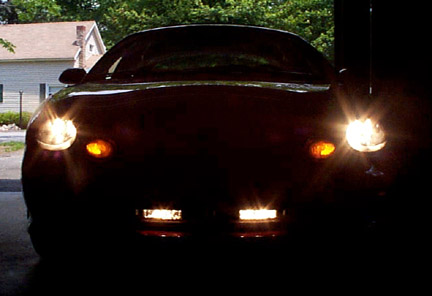
I determined that locating the lamps in the inner quadrants of the
gill was acceptable (Amazing how agreeable I was at this point!) This provided
a few access holes, and even more room to install the lamps. They can be
adjusted somewhat from outside the grill now, minor adjustments mind you.
The mounting points allow for at least an inch of air space behind the
fascia or more if thats your pleasure. This location gives fairly
good rock protection, and a somewhat tunneled appearance when lit (as you
might have noticed from the pictures. I attached the ground wires to the
bumper reinforcing bar with a SS sheet metal screw, as the brass ones that
came with the kit SUCK! I wanted to ensure a real good ground point.
 This kit came with all the wires and the switch which was lighted. The
wiring was more than sufficient to the task. After hooking up the
wires to the lamps, I routed the wiring along the power steering cooler
( I think) upper line. I used the tie wraps that came with the kit.
I routed the wire up behind the front nose piece next to the headlamp assy,
and through a hole in the radiator support coming out next to the battery
box.. 1 Wire.. red, 12
This kit came with all the wires and the switch which was lighted. The
wiring was more than sufficient to the task. After hooking up the
wires to the lamps, I routed the wiring along the power steering cooler
( I think) upper line. I used the tie wraps that came with the kit.
I routed the wire up behind the front nose piece next to the headlamp assy,
and through a hole in the radiator support coming out next to the battery
box.. 1 Wire.. red, 12
ft long. At this point I added the blue battery wire to the red
wire and taped them together as a pair. I routed the wires underneath
the MAF assy and back to the firewall next to the Brake Vacuum canister.
If you take a light and shine it back in there, there is a rubber plug. A sharp coat hanger wire will punch right thru this and into the interior, just above a black electronics box. I didn't take time to notice what it was for. Be careful when removing the coat hangar wire, the plug can and might come out. Once inside I removed the lower dash panel (2 9MM bolts) to access some sheet metal frame for a ground. I was able to reach around the box to access the wires from under the hood and pull them through. I drilled a hole in the lower dash frame and again used a different screw than what came with the kit. The ground wire was attached here, and it was about 10 inches long, so it was plenty long enough.
The switch, the switch, the switch... Where to mount it... Well, I chose to mount it from the bottom of the dash adjacent to where the lower panel comes off. It is above the hood release, and the Emergency brake pedal, and below the brake release. It is out of the way pretty much even for me, and I am clumsy as hell. The switch is fairly small and does not intrude into the cockpit much. I have to reach down to get to it, but I figured, It wont get used THAT often.. or not.. I drilled two holes for the screws from underneath the dash. If this position doesn't work, the holes will not be visible. Three wires... 1) black ground wire, 1) Blue Battery wire, 1) Red lamps wire, all hook up to the switch. Again, it is lighted when on.
At this point, I hooked the other end of the blue wire to the positive
post of the battery. I used more tie-wraps to secure the wires.
I pulled all excess wire into the engine compartment, and made a service
bundle of it, located below the air cleaner.
All I have to do now is to adjust for driving and it is hot to go.