
1. Disconnect battery ground cable.
2. Install Rotunda Three Bar Engine Support D88L-6000-A or equivalent to Spreader Bar D93P-6001-A3 or equivalent and then to Universal Engine Lifting Brackets T70P-6000.
3. Raise vehicle on hoist.
4. Remove front tires and wheels.
5. Support steering gear with wire from the tie rod end to front coil spring to hold steering gear in position. Secure housing of steering gear to suitable support to hold it in position.
6. Remove dual converter Y pipe.
7. Disconnect front suspension lower arms at retaining nuts to ball joints.
8. Remove two nuts that attach steering gear to front sub-frame.
9. Remove retaining nuts from front engine support insulators to front sub-frame.
10. Remove stabilizer bar link attachment from front stabilizer bar.
11. Remove engine and transmission support insulator through bolts from front sub-frame.
12. Disconnect power steering return line mounting braket at LH rear of sub-frame.
13. Remove power steering filter from bracket on inside of LH sub-frame.
14. Support front sub-frame with adjustable jacks at front sub-frame location points.
15. Remove four front sub-frame-to-body insulator retaining bolts.
16. With an assistant, lower adjustable jacks and allow front sub-frame to lower.
17. Place front sub-frame on floor or bench and transfer suspension components to the new front sub-frame.
Installation
1. Install front frame body insulator to the front of RH and LH front sub-frame. Install four nuts to each front frame body insulator and tighten to 8-11 N-m (71-97 lb-in).
2. CAUTION: Do not tighten front sub-frame to body bolts at this time as the front sub-frame MUST be aligned to body prior to tightening retainers.
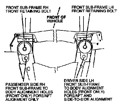
With an assistant, align front sub-frame to body. Install two rear front frame body insulators. Install four front sub-frame-to-body bolts loosely.
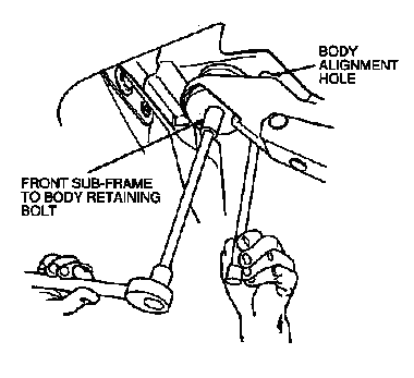
3. Install a 19 mm (3/4 inch) outside diameter pipe or similar tool into front LH front sub-frame and body alignment holes. After aligning the holes, slightly tighten the LH front sub-frame to body bolt.
4. Repeat Step 2 on front RH alignment holes.
5. Check front RH alignment holes with tool.
6. After front sub-frame alignment is complete, tighten four front sub-frame-to-body bolts to 77-103 N-m (57-75 lb-ft).
7. Install engine and transmission support insulator to front sub-frame. Tighten through bolts to 88-118 N-m (65-87 lb-ft).
8. Install stabilizer bar link to front stabilizer bar. Tighten retaining nut to 47-63 N-m (35-46 lb-ft).
9. Install two retaining nuts that secure the steering gear to the front sub-frame. Tighten to 113-133 N-m (84-98 lb-ft).
10. Remove wire supporting steering gear from tie rod end to steering gear.
11. Install retaining nuts that secure the front engine support insulators to the front sub-frame. Tighten to 77-103 N-m (57-75 lb-ft).
12. Connect power steering return line mounting bracket at LH rear of sub-frame.
13. Install power steering filter and bracket on inside of LH sub-frame.
14. Connect front suspension lower arms with retaining nuts to ball joints. Tighten retaining nuts to 68-92 N-m (51-67 lb-ft).
15. Install dual converter Y pipe.
16. Install tires and wheels.
17. Lower hoist.
18. Remove Three Bar Engine Support D88L-6000-A or equivalent and engine lifting eyes.
19. Connect battery ground cable.
20. Check front end alignment. Adjust if necessary.
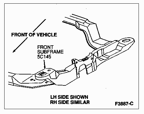
Front Sub-Frame, Top View