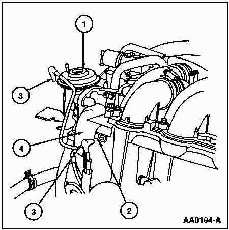

RH Side, Removal
1. Disconnect battery ground cable.
2. Remove engine appearance cover as described.
3. Remove right half of cowl vent screen.
4. Disconnect the main emission vacuum supply hose from the surge tank
vacuum fitting and EGR valve. Position vacuum supply hose out of
the way.

| Item | Part Number | Description |
| 1 | 9D475 | EGR valve |
| 2 | -- | Surge Tank Vacuum Fitting |
| 3 | -- | Main Emission Vacuum Supply Hose |
| 4 | -- | Surge Tank |
6. Disconnect EGR valve to exhaust manifold tube from bottom of EGR valve.
7. Remove power steering left turn pressure hose bracket nut. Position power steering left turn pressure hose aside.
8. Remove the two retaining bolts for the transducer mounting bracket from the surge tank. Position the transducer mounting bracket out of the way.
9. Remove the two intake manifold supports from the surge tank and cylinder head.
Transducer Mounting Bracket and Intake Manifold Support Installation
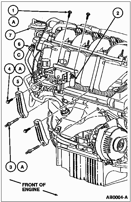
| Item | Part Number | Description |
| 1 | 95027-08016 | Bolt (2 Req'd) |
| 2 | 9J432 | Transducer Mounting Bracket |
| 3 | A9908 | Stud Bolt (2 Req'd) |
| 4 | 95824-08035 | Bolt (2 Req'd) |
| 5 | 9J444 | Intake Manifold Support (2 Req'd) |
| 6 | 9D477 | EGR Valve to Exhaust Manifold Tube |
| 7 | 9D475 | EGR Valve |
| A | -- | Tighten to 18-28 N-m (14-20 Lb-Ft) |
| B | -- | Tighten to 25-35 N-m (19-25 Lb-Ft) |
11. Remove bolt, nuts and surge tank stay from rear of surge tank.
12. Disconnect crankcase ventilation hose.
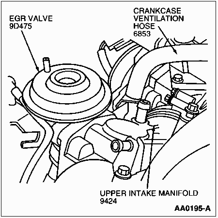
13. Disconnect intake manifold to surge tank ventilation tube.
14. Disconnect vacuum tube to fuel pressure regulator (9C968).
15. Loosen intake air connector hose clamps and remove surge tank from engine.
Surge Tank Installation
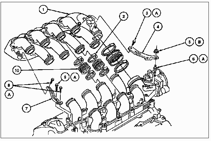
| Item | Part Number | Description |
| 1 | 9424 | Intake Manifold |
| 2 | 8287 | Hose Clamp |
| 3 | 95024-08016 | Flange Bolt |
| 4 | 9J444 | Intake Manifold Support |
| 5 | 95704-06500 | Nut (2 Req'd) |
| 6 | 90116-06606 | Stud Bolt (2 Req'd) |
| 7 | 9J444 | Intake Manifold Support |
| 8 | 95024-08016 | Bolt (2 Req'd) |
| 9 | 95024-08035 | Bolt |
| 10 | 9F722 | Air Tube to Throttle Body Hose |
| A | -- | Tighten to 18-28 N-m (14-20 Lb-Ft) |
| B | -- | Tighten to 5-7 N-m (45-61 Lb-In) |
17. Remove retaining bolts and ignition coil.
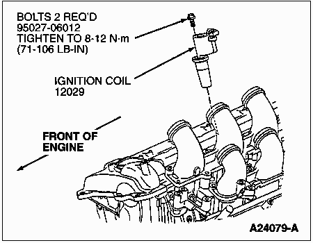
18. Remove two wiring harness guide retaining bolts.
19. Remove two engine sensor control wiring bracket bolts.
20. Remove radio interference capacitor bracket retaining nut.
21. Disconnect crankcase ventilation tube from valve cover.
22. Position engine control sensor wiring aside.
23. Note: Valve cover gasket is reusable if not damaged.
Loosen valve cover retaining bolts and stud bolts and carefully remove valve cover from cylinder head. Remove integral valve cover gasket from RH valve cover.
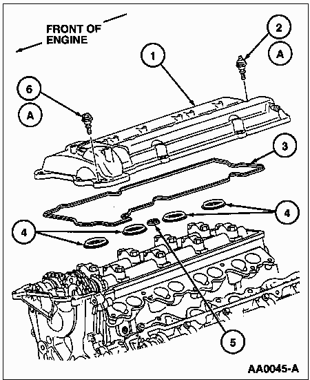
| Item | Part Number | Description |
| 1 | 6582 | Valve Cover |
| 2 | 6A548 | Valve Cover Bolt |
| 3 | 6584 | Valve Cover Gasket |
| 4 | 6F048 | Cylinder Head Cover Gasket (4 Req'd) |
| 5 | 6F048 | Cylinder Head Cover Gasket |
| 6 | 6A548 | Valve Cover Bolt (7 Req'd) |
| A | -- | Tighten to 8-12 N-m (71-106 Lb-In) |
1. Note: Prior to installation, clean valve cover sealing surfaces using a shop towel and Metal Surface Cleaner F4AZ-19A536-RA or equivalent meeting Ford specification WSE-M5B392-A.
Apply 8 mm (0.31 inch) diameter bead of Black Silicone Rubber F4AZ-19562-B or equivalent sealant meeting Ford specification WSE-M4G323-A1 at two places on the valve cover sealing surfaces where the engine front cover and cylinder heads contact.
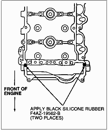
2. Install new valve cover gaskets onto RH valve cover.
3. Position valve cover on RH cylinder head. Install eight valve cover bolts. Tighten valve cover bolts and stud bolts to 8-12 N-m (71-106 lb-in) within six minutes of applying sealer. Position intake air connector hose clamps as indicated.
RH Valve Cover Installation
4. Connect crankcase ventilation tube to valve cover.
5. Position radio ignition interference capacitor bracket on valve cover. Install retaining nut. Tighten retaining nut to 8-12 N-m (71-106 lb-in).
6. Position engine control sensor wiring on valve cover and install two engine sensor control wiring brackets. Install and tighten bracket retaining bolts to 8-12 N-m (71-106 lb-in).
7. Install two wiring harness guide retaining bolts. Tighten bolts to 8-12 N-m (71-106 lb-in).
8. Install four ignition coils and eight ignition coil retaining bolts. Tighten bolts to 8-12 N-m (71-106 lb-in).
9. Connect engine control sensor wiring to four ignition coils.
Surge Tank Installation
10. Position surge tank on engine. Align and tighten clamps as described in intake manifold installation.
Intake Air Connector Hose Clamp Orientation
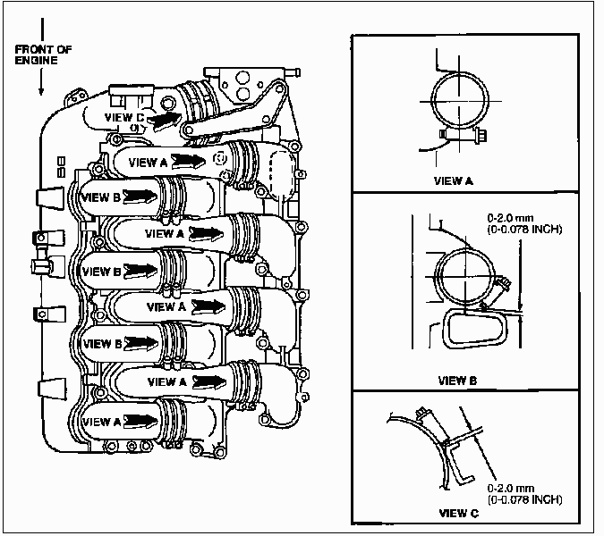
11. Connect intake manifold ventilation tube to surge tank vacuum port.
12. Connect crankcase ventilation hose to valve cover.
13. Position rear surge tank stay and install retaining bolt and two retaining nuts. Tighten retainers to 18-28 N-m (14-20 lb-ft).
14. Position front surge tank stay and install retaining bolts. Tighten bolts to 18-28 N-m (14-20 lb-ft).
15. Install two intake manifold supports on the surge tank and cylinder head. Install and tighten retaining nuts and bolts to 18-28 N-m (14-20 lb-ft).
16. Position transducer mounting bracket to surge tank and install two retaining bolts. Tighten bolts to 18-28 N-m (14-20 lb-ft).
Transducer Mounting Bracket and Intake Manifold Support Installation
17. Position power steering left turn pressure hose on surge tank stud bolt and install retaining nut. Tighten nut to 8-12 N-m (71-106 lb-in).
18. Connect EGR valve to exhaust manifold tube to EGR valve. Tighten fitting to 25-35 N-m (19-25 lb-ft).
19. Connect vacuum tube to intake manifold vacuum union.
20. Connect main emission vacuum supply hose to surge tank vacuum fitting and EGR valve.
21. Install cowl vent screen.
22. Install engine appearance cover as described.
23. Connect battery ground cable.
LH Side, Removal
1. Disconnect battery ground cable.
2. Remove engine appearance cover as described.
3. Disconnect the engine control sensor wiring from the intake manifold runner control (IMRC) deactivation motor.
4. Remove engine control sensor wiring from wire harness bracket and wire harness clamp.
5. Remove two wire harness bracket retaining bolts.
6. Remove three retaining bolts for the IMRC deactivation motor from the LH valve cover and position the IMRC deactivation motor out of the way.
7. Disconnect engine control sensor wiring connector from ignition coils.
8. Remove retaining bolts and ignition coils.
9. Disconnect ignition capacitor connector.
10. Disconnect crankcase ventilation tube from valve cover.
11. Raise vehicle.
12. Remove radiator air deflector.
13. Disconnect engine control sensor wiring from A/C pressure cutoff switch and crankshaft position sensor (CKP sensor).
14. Disconnect engine control sensor wiring from A/C compressor clutch field coil and heated oxygen sensor connectors.
15. Slide heated oxygen sensor connector off Christmas tree retainer.
16. Remove two engine sensor control wiring to engine front cover retaining nuts. Position engine control sensor wiring aside.
17. Lower vehicle.
18. Remove right hand wiring harness guide retaining nut.
19. Position engine control sensor wiring aside.
20. Remove degas tube bracket retaining bolt.
21. Remove two wire harness clip retaining bolts and wire harness clip.
Ignition Coil and IMRC Deactivation Motor Installation
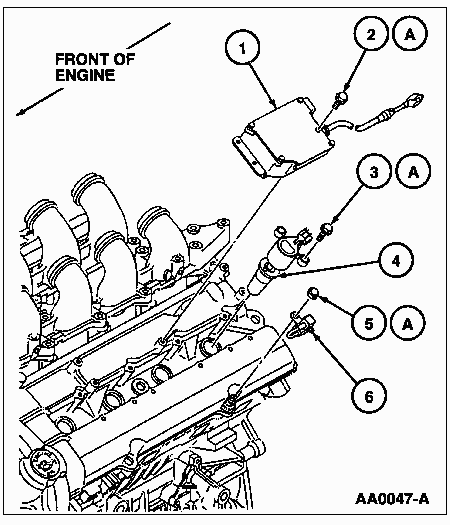
| Item | Part Number | Description |
| 1 | 9L496 | IMRC Deactivation Motor |
| 2 | 95827-06012 | Retaining Bolt (3 Req'd) |
| 3 | 95027-06020 | Bolt (2 Req'd) |
| 4 | 12029 | Ignition Coil |
| 5 | 95317-06700 | Hex Nut |
| 6 | 18801 | Ignition Capacitor |
| A | -- | Tighten to 8-12 N-m (71-106 Lb-In) |
Loosen bolts and stud bolts and carefully remove valve cover from LH cylinder head. Remove integral valve cover gasket from LH valve cover.
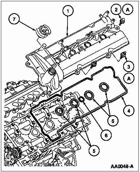
| Item | Part Number | Description |
| 1 | 6582 | Valve Cover |
| 2 | 6A548 | Valve Cover Bolt (6 Req'd) |
| 3 | 6A548 | Valve Cover Bolt (2 Req'd) |
| 4 | 6584 | Valve Cover Gasket |
| 5 | 6F048 | Cylinder Head Cover Gasket (4 Req'd) |
| 6 | 6F048 | Cylinder Head Cover Gasket |
| 7 | 6766 | Oil Filler Cap |
| A | -- | Tighten to 8-12 N-m (71-106 Lb-In) |
1. Note: Prior to installation, clean valve cover sealing surfaces using a shop towel and Metal Surface Cleaner F4AZ-19A536-RA or equivalent meeting Ford specification WSE-M5B392-A.
Apply 8 mm (0.31 inch) diameter bead of Black Silicone Rubber F4AZ-19562-B or equivalent sealant meeting Ford specification WSE-M4G323-A1 at two places on the valve cover sealing surfaces where the cylinder heads contact and at two places on the rear of the cylinder head where the camshaft seal retainer contacts the cylinder head.
2. Install new valve cover gaskets onto LH valve cover.
3. Position valve cover on cylinder head. Install eight retaining bolts. Tighten valve cover bolts and stud bolts to 8-12 N-m (71-106 lb-in) within six minutes of applying sealer.
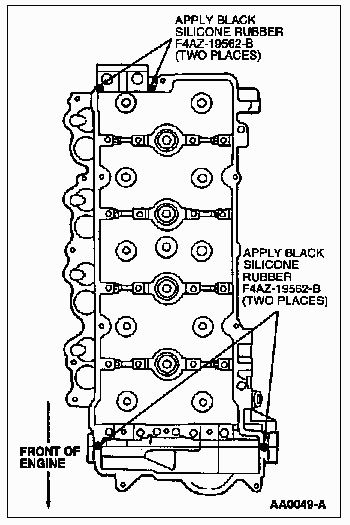
4. Install wire harness clip and two retaining bolts. Tighten bolts to 8-12 N-m (71-106 lb-in).
5. Install degas tube bracket and retaining bolt. Tighten bolt to 8-12 N-m (71-106 lb-in).
6. Position engine control sensor wiring on valve cover.
7. Install RH wiring harness guide nut. Tighten to 8-12 N-m (71-106 lb-in).
8. Raise vehicle.
9. Position engine control sensor wiring on front cover stud bolts and install two retaining nuts. Tighten nuts to 8-12 N-m (71-106 lb-in).
10. Slide heated oxygen connector on Christmas tree retainer.
11. Connect engine control sensor wiring to A/C compressor clutch field coil and heated oxygen sensor connectors.
12. Connect engine control sensor wiring to A/C pressure cut-off switch and crankshaft position sensor.
13. Install radiator air deflector.
14. Lower vehicle.
15. Connect crankcase ventilation tube to valve cover.
16. Connect engine control sensor wiring to ignition capacitor connector.
17. Install ignition coils and retaining bolts. Tighten bolts to 8-12 N-m (71-106 lb-in).
18. Connect engine control sensor wiring to ignition coils.
19. Position IMRC deactivation motor on valve cover. Install three retaining bolts. Tighten retaining bolts to 8-12 N-m (71-106 lb-in).
20. Position wiring harness bracket on valve cover. Install two retaining bolts. Tighten bolts to 8-12 N-m (71-106 lb-in).
21. Install engine control sensor wiring in wire harness bracket and wire harness clamp.
22. Connect engine control sensor wiring to intake manifold runner control (IMRC) deactivation motor.
23. Install engine appearance cover as described.
24. Connect battery ground cable.